Okay, die erste Uhr haengt. Hier werde ich den Bau der zweiten Uhr dokumentieren.
Das wird ein Sammelsorium aber irgendwann raueme ich das auf, versprochen!
1. Die Theorie
Die neue Uhr soll mit einem Chip von Austria Microsystems betrieben werden der insgesamt 132 LEDs ansteuern kann. Fuer die Uhr braucht man aber “nur” 114. Des weiteren soll als Uhr ein DS3232 zum Einsatz kommen, im Gegensatz zum vorher verwendeten DS1307 hat dieser Chip den Quarz eingebaut und ist daher genauer. Das Problem bei beiden Chips ist ihre Groesse aber dazu spaeter mehr. Des weiteren werde ich einen Arduino Nano zur Steuerung des ganzen verwenden und als LEDs werden wieder Superflux LEDs verwendet.
Das ist mein Schaltplan. Gestrichelte Linien sind Verbindungen auf der Rueckseite der Platine des Chips um die Anzahl der langen Verbidnungsleitungen zu minimieren.
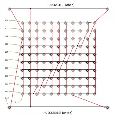
und das ist die LED Matrix (Superflux LEDs), Version 2. Achtung man sieht die Rueckseite, die Eck-LED oben rechts auf diesem Bild ist bei der Uhr dann oben links und die Eck-LED #1.
Die Matrix funktioniert schonmal
Der Testcode basiert auf dem von Bernhard Göberndorfer Die Helligkeit wird im Moment noch ueber den Stromfluss geregelt, das muesste aber eigentlich (eleganter) auch ueber PWM moeglich sein. Wenn man die LEDs “anstellt” muessen die vorderen 4 Bits bei as_config(0x01, 0x01, 0b00000000); “0” sein, sonst leuchtet gar nichts (also nicht einfach alle Bits auf 1 setzen!). Warum das so ist kann man im Datenblatt sehen (es sind die PWM sets).
/*
 Example Sketch for AMS AS1130 LED DRIVER.
 This is in public domain.

 2012-05-04 Max Gruening
 Code basiert auf untem genannten. zum testen habe ich ihn aber verschlankt und ein wenig angepasst
 2012-03-07 Göberndorfer Bernhard
 code@kokosnuss.org
 refers to datasheet http://www.austrianmicrosystems.com/Products/Lighting-Management/LED-Driver-ICs/AS1130 in Rev 1.04
*/

#include <Wire.h>

// AS1130 I2C Address - tbl.6/p.12
#define AS1130ADDRESS 0x30  // 0x30 = default if PIN 17 open

uint8_t wire_write(uint8_t command, uint8_t data)
 {
 Wire.beginTransmission(AS1130ADDRESS);
 Wire.write(command);
 Wire.write(data);
 int ack = Wire.endTransmission();
 if (ack != 0) {
  Serial.print("ERROR: ");
  Serial.print(ack);
 }
 return ack;
}

void as_config(uint8_t ram, uint8_t command, uint8_t data)
{
 wire_write(0xfd, ram);
 wire_write(command, data);
}

void allonoff(double onoff1, double onoff2)
{
 /* set every bit in On/Off Frame 0-35 to 0 */
 for (int i=0x01; i<=0x24; i++) {
  for (int o=0x00; o<=11; o++) {
   as_config(i, 2*o, onoff1);
   as_config(i, 2*o+1, onoff2);
  }
 }
}

void setup()
{
 // Serial.begin(57600);
 // Serial.println("AS1130 example code");
 Wire.begin(); // start up I2C bus
 //Register des AS1130 setzen
 as_config(0xc0, 0x00, 0b01000000); // 0b01000000 = display picture
 as_config(0xc0, 0x01, 0x00);
 as_config(0xc0, 0x02, 0x00);
 as_config(0xc0, 0x03, 0x00);
 as_config(0xc0, 0x04, 0X0B); // 0b1011 = CS0 to CS11
 as_config(0xc0, 0x05, 0x80); // current source 15mA
 as_config(0xc0, 0x06, 0x01); // ram configuration 1
 as_config(0xc0, 0x07, 0x00);
 as_config(0xc0, 0x08, 0x00);
 as_config(0xc0, 0x09, 0x00); // 0x03 = licht an
 as_config(0xc0, 0x0A, 0xff); // 0xff = default
 as_config(0xc0, 0x0B, 0x00); // 0x00 = default

 // set Blink Set 1 to 0
 // sonst blinken die LEDs unkontrolliert
 // mit ramconf=1 haben wir nur ein Blinkset, sost muss das auch fuer die anderen gemacht werden
 for (int o=0x00; o<=0x17; o++) {
  as_config(0x40, o, 0x00);
 }
 allonoff(0x00,0x00); //erstmal alles ausmachen
}

void loop()
{
 allonoff(0xFF,0x1F);

 as_config(0xc0, 0x09, 0x03); // jetzt einschalten

 //dimmen
 byte brightn=0;
 do {
  as_config(0xc0, 0x05, brightn); // current
  delay(20);
  brightn++;
 } while (brightn<255);

 do {
  as_config(0xc0, 0x05, brightn); // current
  delay(20);
  brightn--;
 } while (brightn>0);
allonoff(0x00,0x00);
delay(1000);
as_config(0xc0, 0x05, 90); //Helligkeit auf 90 setzen

//Smiley
 as_config(0x01, 0x00, 0b00000000);
 as_config(0x01, 0x01, 0b00000000);
 as_config(0x01, 0x02, 0b11111000);
 as_config(0x01, 0x03, 0b00000000);
 as_config(0x01, 0x04, 0b00000100);
 as_config(0x01, 0x05, 0b00000001);
 as_config(0x01, 0x06, 0b10001010);
 as_config(0x01, 0x07, 0b00000010);
 as_config(0x01, 0x08, 0b00000010);
 as_config(0x01, 0x09, 0b00000010);
 as_config(0x01, 0x0A, 0b10001010);
 as_config(0x01, 0x0B, 0b00000010);
 as_config(0x01, 0x0C, 0b01110010);
 as_config(0x01, 0x0D, 0b00000010);
 as_config(0x01, 0x0E, 0b00000100);
 as_config(0x01, 0x0F, 0b00000001);
 as_config(0x01, 0x10, 0b11111000);
 as_config(0x01, 0x11, 0b00000000);
 as_config(0x01, 0x12, 0b00000000);
 as_config(0x01, 0x13, 0b00000000);
 as_config(0x01, 0x14, 0b00001111);
 as_config(0xc0, 0x09, 0x03); //einschalten

 delay(3000);

 //Eck-LED test
 as_config(0x01, 0x14, 0b00000001);
 as_config(0xc0, 0x09, 0x03);
 delay(1000);
 as_config(0x01, 0x14, 0b00000010);
 as_config(0xc0, 0x09, 0x03);
 delay(1000);
 as_config(0x01, 0x14, 0b00000100);
 as_config(0xc0, 0x09, 0x03);
 delay(1000);
 as_config(0x01, 0x14, 0b00001000);
 as_config(0xc0, 0x09, 0x03);
 delay(1000);
 as_config(0x01, 0x14, 0b00000001);
 as_config(0xc0, 0x09, 0x03);
 delay(1000);
 as_config(0x01, 0x14, 0b00000011);
 as_config(0xc0, 0x09, 0x03);
 delay(1000);
 as_config(0x01, 0x14, 0b00000111);
 as_config(0xc0, 0x09, 0x03);
 delay(1000);
 as_config(0x01, 0x14, 0b00001111);
 as_config(0xc0, 0x09, 0x03);
 delay(1000);
 as_config(0xc0, 0x09, 0x00);
 delay(2000);
}

/*
Binary Hex Conversion Chart Table
Binary 0000 0001 0010 0011 0100 0101 0110 0111 1000 1001 1010 1011 1100 1101 1110 1111
Hex      0    1    2    3    4    5    6    7    8    9    A    B    C    D    E    F
*/
Front (45×45 cm)


Hi Max!
Danke für die Anerkennung.
nettes Video 🙂
Habe mich jetzt länger nicht mehr mit der Thematik beschäftigt, aber der perfekte Platz an der Wand wartet bereits auf meine nächste Uhr; Da kommt die kalte Jahreszeit jetzt genau richtig. Wir werden da schon einen coolen Code zusammenbringen!
lg Bernhard